Home / Guide / Connectables: holes for real hardware
Guide 7 of 12Connectables: holes for real hardware
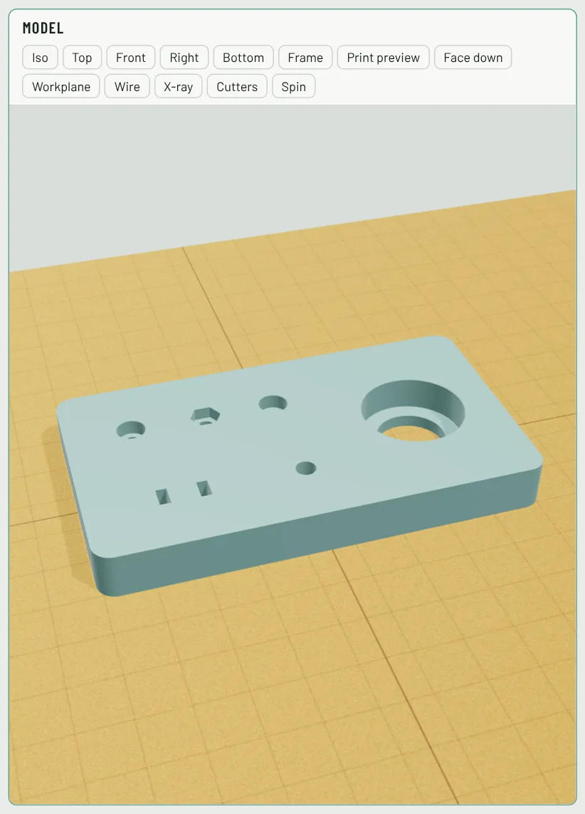
Pick the hardware and its size, and Extrudable3D cuts a hole that fits it: the right clearance for an M3 screw, a pocket for its head, a hex trap for its nut, a seat for a 608 bearing. No looking up tables.
- Open the shape library (B) and pick one under Connectables, or press Ctrl+K and type what you have, such as m3 insert or 608.
- Click on the part where it goes. It sinks into that part's top, cutting exactly its Depth from the surface. In 3D you can click a side face too: it lies down and goes into that side.
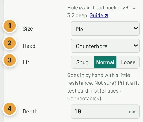
- Choose the Size (and the Head of a screw). The note at the top of the panel lists the real sizes it cuts.
- Leave Fit on Normal unless your fit test card says otherwise.
What there is
- Screw hole, M2 to M8 and #4-40, #6-32, #8-32, 1/4-20: Counterbore (the head sits below the surface), Countersink (for flat-head screws), Plain hole, or Self-tap (a smaller hole the screw cuts its own thread into).
- Nut trap: a hex pocket with the screw hole through it. Drop in from the top, or Slide in from the side: a slot the nut slides along, buried a few millimetres below the face. Turn the part to aim the slot at an edge.
- Heat-set insert, M2 to M8: the hole size printed on common brass inserts, deep enough for the insert plus a little room for the melted plastic.
- Magnet: round magnets from 3 × 1 to 20 × 5 mm (diameter × thickness).
- Bearing: 623, 625, 688 and 608 (skateboard) ball bearings. The seat has a ledge under the outer ring only, so the inner ring turns freely.
- Pin hole for 2–8 mm dowel pins, LED hole for 3 mm and 5 mm LEDs, and Zip-tie slots: a pair of slots for a cable tie to loop through.
The sizes come from the published standards: clearance holes from ISO 273 (and the usual inch drill sizes), screw heads from ISO 4762 and ISO 10642, nuts from ISO 4032. A connectable keeps its real size, so it has no width handles; pick another Size instead. It is always a hole.
Fit: snug, normal or loose
Printed holes usually come out a little smaller than drawn, and how tight a part should sit depends on the job.
- Snug: a press fit. Magnets and pins stay put without glue; you may need to push or tap them in.
- Normal: goes in by hand with a little resistance. The right choice for most printers.
- Loose: drops in. Use it when your printer makes holes small, or glue the part in.
For screw holes the three fits are the ISO 273 fine, medium and coarse clearances (3.2, 3.4 and 3.6 mm for M3).
Fit test card
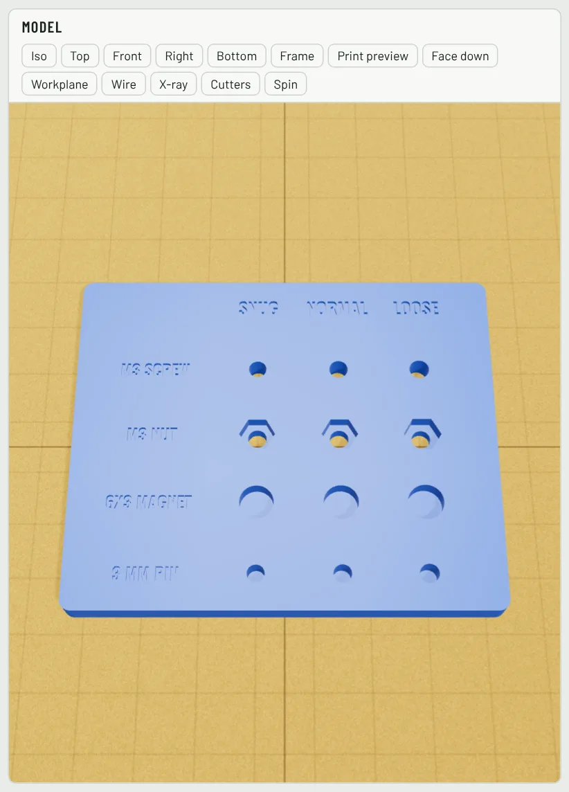
Before printing the real part, add a Fit test card from the library and print it (it takes a few minutes). Try your screw, nut, magnet and pin in each column and use the fit that feels right on your parts from then on. Each hole on the card is a normal connectable: select it (double-click inside the group) and change its size to test the hardware you actually have.
Questions
Which fit should I use?
Normal suits most printers. If you are unsure, print the fit test card from the library: it takes a few minutes and shows how tight snug, normal and loose come out on your printer.
Why does the hole start 0.5 mm above the surface?
So the cut is clean. The connectable reaches just past the face it sits on; its Depth is measured from that face.
Can I make the hole deeper?
Yes: change Depth in the panel, or drag the top arrow in 3D. A screw hole that must go all the way through just needs a Depth at least as thick as the part.